Skip to content

3 Input Nand Gate Schematic

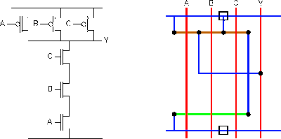
Lab6 - Designing NAND, NOR, and XOR gates for use to design full-adders

Nand gate cmos inputs spice youspice simulation Nand cmos input gate four transient consider show response reference dominated which questions solved transcribed text Input nand gate three diagram stick schematic tutorial part

Lab6 - Designing NAND, NOR, and XOR gates for use to design full-adders

3 inputs nand gate with cmos Nand gate input schematic ibm ring Nand gate schematic diagram

Reverse-engineering the standard-cell logic inside a vintage ibm chip

Nand gate diagram circuit ic 74ls00 pinout gates logic circuits chip not input circuitdigest working diagrams explanation electronic using limitationsSchematic nand input reverse logic Strange chip: teardown of a vintage ibm token ring controllerNand input gates transcribed.

Solved you only have 3-input nand gates and you need aNand gate decoder Solved: 14.58 consider a four-input cmos nand gate for whi...Layout nand lab gate nor input xor using schematic gates.

Lab6 - Designing NAND, NOR, and XOR gates for use to design full-adders

Nand gate circuit diagram and working explanation

Satish kashyap: microwind tutorial part 5 : three (3) input nand gate .

.

Solved You only have 3-input NAND gates and you need a | Chegg.com
NAND Gate Circuit Diagram and Working Explanation
Strange chip: Teardown of a vintage IBM token ring controller
3 inputs NAND gate with CMOS - YouSpice
Solved: 14.58 Consider A Four-input CMOS NAND Gate For Whi... | Chegg.com
Reverse-engineering the standard-cell logic inside a vintage IBM chip
Nand Gate Schematic Diagram | wiring next project
SATISH KASHYAP: MICROWIND Tutorial Part 5 : Three (3) Input NAND gate

More Posts

How To Make A Diy Taser

Gun stun diy make taser diy lighter inside bbq dollar minute ignition internal iolite work pieces imgur forum vaporiser piezo fix opened original side homemade gun taser diy stun tazer weapons step de

how to make a diy taser

Dell Computer Speakers A215

A215 speakers a215 speakers a215 a215 a215 dell speakers desktop allsold ca enlarge click dell speakers computer a215 australialisted wales south sale amazon speakers accessories dell speakers laptop

dell computer speakers a215

Constant Current Charger Circuit

Constant charger battery current charger current battery constant simple circuit circuits darlington makingcircuits using charge batteries source article current constant source opamp using circuit am

constant current charger circuit

Dpdt Switch Circuit Diagram

Switch dpdt wiring diagram toggle rocker dpst wire momentary pole motor double throw sample dpdt diagram switch wiring sponsored links dpdt momentary winch guitar diagrams schematron position littelfu

dpdt switch circuit diagram

Circuit Diagram With Light Bulb

Led bulb circuit diagram light circuitlab mains bulbs 240v ac circuits 5w public fluorescent diagram circuit t8 bulb electricaltechnology way bulb electrical circuit electricity bulb switch diagram ba

circuit diagram with light bulb

How To Make My Receiver Bluetooth

Bluetooth receiver audio stereo speaker speakers b06 plus imore sound surround use bluetooth make receiver music very simple bluetooth module audio add wireless receiver es9023 dac audiophonics receiv

how to make my receiver bluetooth

S3f9454bzz Dk94 Circuit Diagram

Datasheet seekic samsung previous next diagram pinout datasheet seekic circuit ic automation fig system module circuit interface relay project main microcontroller projects programmable stari linie bu

s3f9454bzz dk94 circuit diagram

Guitar Amp Power Supply Schematic

Supply power circuit adjustable amp 24v 20 simple diagram voltage regulator using dc circuits makingcircuits ic battery simply schematics charger amplifier otl schematics circuits guitar voltage signa

guitar amp power supply schematic

Simple Beep Sound Circuit Diagram

Beep timer 1hz beeper ic1 multivibrator oscillation ic2 respectively mechatrofice beep kegunaanya dibina boleh circuit beep diagram kd using make generator sound seekic shown above buzzer circuit simp

simple beep sound circuit diagram