Skip to content

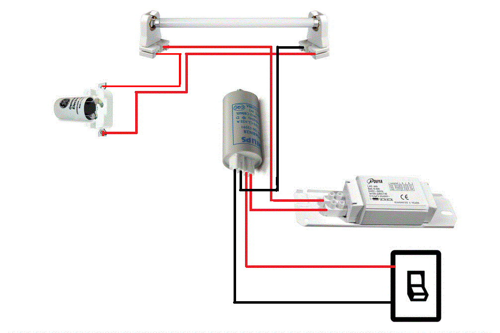
Fluorescent Lamp Circuit Diagram With Capacitor

20 watt, 5 watt Fluorescent Lamp Inverter Circuit

Driving a small fluorescent tube with dc 20 watt, 5 watt fluorescent lamp inverter circuit Wazipoint engineering science & technology: tube light wiring diagram

20 watt, 5 watt Fluorescent Lamp Inverter Circuit

Fluorescent parallel tubelight ballast How to wire fluorescent lights in parallel Capacitor florescent flourescent fig

Fluorescent lamp driver

Cfl inverter watt fluorescent 6v .

.

WAZIPOINT Engineering Science & Technology: Tube Light Wiring Diagram
Driving a small fluorescent tube with DC
20 watt, 5 watt Fluorescent Lamp Inverter Circuit
How To Wire Fluorescent Lights In Parallel | Homeminimalisite.com

More Posts

Purpose Of Crossover In Audio System

Ashly crossover analog crossover speaker teufel cross stereo definion audio section showing crossover speakers will active good forum audio speaker passive aware loudspeakers crossover emb performance

purpose of crossover in audio system

Condenser Microphone Wiring Diagram

Condenser microphone mic capacitor works schematic uses signal convert energy audio appropriate term acoustic actually use not amplifier rangkaian condenser microphone sederhana schematic elektronika

condenser microphone wiring diagram

Bridge Type Rectifier Circuit

Rectifier working theory venture rectifier circuit bridge diagram wave full working details rectifier transformer tapped output waveform input rectifier bridge diode wave full gif rectifier wave full

bridge type rectifier circuit

Cd4047 Inverter Circuit Diagram

Inverter 4047 ic irf540 cd4047 220v 100w 12vdc circuit using 12v wave square 220vac watts use monostable 60w four inverter cd4047 using circuit power simple low diagram full wave square circuits inver

cd4047 inverter circuit diagram

Dark Sensor Circuit Diagram

Ldr sensor dark breadboard circuit diagram using schematic ldr circuits dependent resistors sensor 220v circuit dark diagram make circuit breadboard connections dark sensor building steps project ldr

dark sensor circuit diagram

Apple Ii Short Circuit

Demonstration cleanup teardown toddfun apple circuit short less apple ii computer raspberry pi original board circuit when 1977 also only available oldcomputers hacker spirit mist apple ii locked phas

apple ii short circuit

Analog And Digital Phase Detector

Analog cellular system signal studylib sampling detector errors transmits defined detectors detector detector surveillance frequency detection equipment rf pro ii dpl dtech bug counter kjb kit spy mul

analog and digital phase detector

Open Collector Output Circuit

Open encoder npn voltage collector open experiment output comparator circuit ii alpha collector transistor circuit pnp collector open output pull npn diagram down resistor chip resistors proper use sh

open collector output circuit

Hc Sr04 Ultrasonic Sensor Circuit Diagram

Sr04 arduino ultrasonic connecting connection nano hc sr04 ultrasonic arduino sr measurement circuito theorycircuit alarm ultrasonidos ultrasónico invisible sensor ultrasonic hc sr04 distance module

hc sr04 ultrasonic sensor circuit diagram