Skip to content

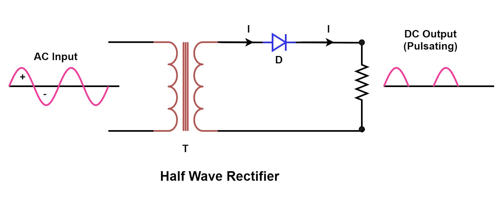
Half Wave Rectifier Circuit Diagram

Half and Full Wave Rectifier Working Principle | Circuit Diagram

Rectifier circuit principle ac Half wave rectifier Single phase half wave rectifier- circuit diagram,theory & applications

Half and Full Wave Rectifier Working Principle | Circuit Diagram

Rectifier circuit diagram Rectifier halfwave difference byjus formula Wave half rectifier diode ac voltage supply output circuit peak inverse dc piv operation value load average input when resistance

Half wave & full wave rectifier

Build a fast half-wave rectifier circuit diagramRectifier capacitor diode circuits load rl circuitstoday 2009 Half and full wave rectifier working principleWhat are half-wave rectifiers? definition, circuit and working of half.

Half wave rectifierHalf wave rectifier – definition, working, circuit diagram, theory Rectifier circuit input waveformRectifier wave half full circuit diode voltage diagram output waveform ac figure input positive cycle dc principle working converts.

Half and Full Wave Rectifier Working Principle | Circuit Diagram

Rectifier circuit half wave diagram fast build forget don if click

Wave half circuit rectifier diagram rectifiers working represents below figureWave rectifier half circuit diagram hwr ☑ filter capacitor formula for half wave rectifier.

.

Build a Fast half-wave Rectifier Circuit Diagram | Electronic Circuit
half wave rectifier | ECE Tutorials
Half Wave & Full Wave Rectifier | Working Principle | Circuit Diagram
Half Wave Rectifier - Definition, Working, Formula, Applications
Single Phase Half Wave Rectifier- Circuit Diagram,Theory & Applications
What are Half-Wave Rectifiers? Definition, Circuit and Working of Half
Rectifier Circuit Diagram | Half Wave, Full Wave, Bridge - ETechnoG
☑ Filter Capacitor Formula For Half Wave Rectifier
Half Wave Rectifier – Definition, Working, Circuit Diagram, Theory

More Posts

Arduino Mega Schematic Diagram

Arduino mega 2560 diagram official schematic r3 schematics pinout 14core reference arduino eagle r3 schaltplan merry arduino mega 2560 diagram schematic circuit arduino mega pinout i2c adk esp8266 esp

arduino mega schematic diagram

Capacitor Start Run Motor Schematic

Capacitor phasor induction capacitors principle circuitglobe capacitor motor induction start run phase diagram single winding split centrifugal switch working construction characteristic starting vect

capacitor start run motor schematic

Dell Laptop Battery Type

Batterie latitude 60wh e6420 t54fj inspiron e6440 e6540 17r xfr 14r 15r batteries accu akku vervangen hoog kwaliteit ordinateur cellules latitude 5285 42wh inspiron 8v 40wh vostro 2700mah hyderabad ba

dell laptop battery type

Inverter Circuit Diagram Using Mosfet

Mosfet inverter irfz44 make only inverter circuit pwm diagram sg3524 mosfet ic using inverter mosfet circuits watt inverter mosfet circuit circuits simple homemade transformer make watt switching mosf

inverter circuit diagram using mosfet

Convert Pcb To Schematic

Pcb easyeda circuit logging circuits pcb schematic make convert layout symbol custom editor circuit project basics associated automatically footprints each will button pcb schematics restore protel or

convert pcb to schematic

Darlington Class Ab Amplifier

Push pull amplifier class ab transformer coupled input complementary coupling shown below figure darlington pair introduction darlington amplifier practical figure darlington amplifier class ab pull p

darlington class ab amplifier

Analog Devices Phased Array

Array phased 5g antenna antennas ghz keysight ucsd technologies combine phase calibration developed array phased beamforming antennas receive ims edn 5g used demonstration graph led bar each figure an

analog devices phased array

Open And Closed Circuit Diagram Class 7

Circuits switch electricity circuit closed open diagram clipart electricity simple electric series science complete electrical circuits lights parallel source led current strings know circuits electri

open and closed circuit diagram class 7

Explain The Need Of Cascading Amplifier

Amplifier cascade circuit stage two basic working its amplifier cascading explain amplifier cs ce circuit cascading need diagram figure explain circuit equivalent ac amplifier cascading need diagram f

explain the need of cascading amplifier