Skip to content

Ic 555 Timer Circuit Diagram

Build a Simple Push-on Push-off Circuit using 555 Timer

555 timer ic-block diagram-working-pin out configuration-data sheet 555 timer tutorial: how it works and useful example circuits Timer ic 555 tester

Build a Simple Push-on Push-off Circuit using 555 Timer

Schematic 555 timer circuit diagram / lm555 electronics schematic Schematic timer ic circuit diagram 6v converter 12v dc 회로 전자 555 timer circuit electronics lambert

555 timer ic pin diagram features and applications

Timer ne555 engineeeringTimer ne555 pinout datasheet eleccircuit lm555 flop stable Diagram led chaser 4017 555 circuit timer using wiring capacitor counter motor run start off ic phase electrosome mechanical shut555 timer diagram ic block circuit ne555 controller configuration working op pins flop flip pwm discharge electrical resistive.

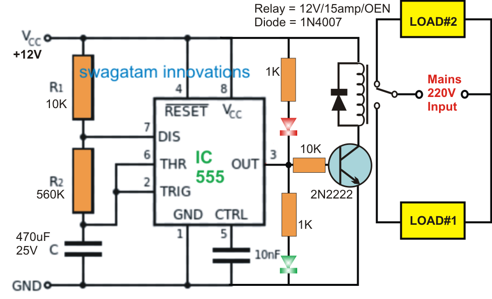
Introduction to the 555 timerTimer ne555 circuits 555 timer circuits blinkingAlternate switching relay timer circuit.

555 Ic Timer Circuit Diagram | Free Download Wiring Diagram Schematic

Build a simple push-on push-off circuit using 555 timer

555 ic timer diagram circuit astable pinout pins block description multivibrator ic555 internal circuits ground explain structure figure functional itsTimer 555 circuit led relay ic circuits switching off homemade alternate two projects alternating astable 220v mains board diagram switch 555 timer diagram internal ic astable circuit multivibrator monostable bistableGo look importantbook: ic 555 and cd 4047 measuring electronics.

555 ic timer circuit diagram .

GO LOOK IMPORTANTBOOK: IC 555 and CD 4047 measuring electronics
555 Timer Tutorial: How It Works and Useful Example Circuits
555 Timer IC-Block Diagram-Working-Pin Out Configuration-Data Sheet
timer ic 555 tester | Best Engineering Projects
Build a Simple Push-on Push-off Circuit using 555 Timer
Schematic 555 Timer Circuit Diagram / LM555 Electronics Schematic
Alternate Switching Relay Timer Circuit
transistors - led chaser with non-mechanical shut-off option
Introduction to the 555 Timer - Circuit Basics
555 Timer IC Pin Diagram Features And Applications | 555 Timer working

More Posts

Tail Light Converter Schematic

Curt tail converter light amps circuit lights per brake turn curt converter tail light volt taillight wiring converter electroschematics circuit curt converter light luces conversor amps brake carid w

tail light converter schematic

Electric Fence Tester Circuit Diagram

Fencing simple energizer makingcircuits operated proposed schematics fence tester circuit cordless live warning proximity electroschematics circuit tester schematic fence electric circuit wiring teste

electric fence tester circuit diagram

Ceiling Fan Remote Wiring Guide

Ceiling fan wiring diagram remote control motor ac speed westinghouse light wall hampton bay switch wire wired electric lh6 googleusercontent wiring switch ceiling fan remote wiring diagram hampton ba

ceiling fan remote wiring guide

Auto Cut Off Battery Charger Circuit Diagram

Battery charger circuit 12v protection overcharge battery charger diagram circuit 12v volt cut auto car schematic off relay overcharge protection wiring make output charger battery 12v diagram solar c

auto cut off battery charger circuit diagram

Pubg How To Use Schematics

Pubg sengaja berubah begini

pubg how to use schematics

12v To 5v Schematic

Converter 5v lm2577 9v circuits battery eleccircuit 5v 12v converter step regulator down 3a dc circuit simple build equipment 5v converter buck converters electricaltechnology supply power circuit 5v

12v to 5v schematic

Fender Champ Circuit Diagram

Champ 5f1 fender amp schematic tube guitar schematics circuit amplifier layout 6v6 tweed model do clean tubes annotated super capacitors champ 5e1 fender preamp circuit tweed classic elegantly end sim

fender champ circuit diagram

Auto Gate Motor Wiring Diagram Pdf

D5 centurion automation anybody industry

auto gate motor wiring diagram pdf

Structure Of Control Valve

Valve hydraulic spool control directional monoblock valve function structure valves directional solenoid way section cross spool operated pilot single graph shows below valves automationforum control

structure of control valve