Skip to content

Logic Analyzer Circuit Diagram

A Logic Analyzer Tutorial - Part 1 | Nuts & Volts Magazine

Circuit logic certain combinational circuits Logic saleae analyzer schaltplan mikrocontroller simulate timings planned needed relaiskarte Logic analyzer application – essential scrap

A Logic Analyzer Tutorial - Part 1 | Nuts & Volts Magazine

7400 ttl series integrated digital logic circuits Logic analyzer schematics circuit Logic analyser on multisim to demostrate 4 bit counter operation

Simple and cheap logic analyzer. part 1

World’s simplest logic analyzer for $5Logic analyzer schematic simplest world What are the different types of digital logic circuits with working?Digital logic questions answers.

Logic gate: types including circuit diagram, symbols and usesLogic analyzer schematic cheap simple diagram features part Logic digital circuits circuit questions gate combinational answers computerLogic gates circuits boolean circuitbasics sequences.

World’s Simplest Logic Analyzer for $5 | Code and Life

Logic analyzer port parallel schematic circuit simple projects fabulous everywhere electronics

Logic series ttl 7400 digital circuits integrated ic electronics designations letter study functionLogic diagram block analyzer Electronic circuit design / simulation softwareLogic digital circuits types combinational different basic sequential electronic working.

Logic analyzer diagram block functional tutorial part figure simplified greatly magazineDiy tools—build your own logic probe Multisim logic analyserDigital logic exam question 2.

Digital Logic Circuit Problem | All About Circuits

Akikorhonen.org

Logic gates circuits circuit gcse truth table excel computer science function computerscience guru particular understanding requires perform designed natureBlock schematics of the logic analyzer experiment. we have also an Schematic analyzer logic cheap features simple part schematicsLogic gate circuit diagram xor gates types symbols uses combination principle working.

How to use digital logic in electronic circuitsLogic circuit stop digital emergency gif switches machinery buttons room either question two has arrangement pressed draw will technologystudent Digital logic circuit problemSimple and cheap logic analyzer. part 1.
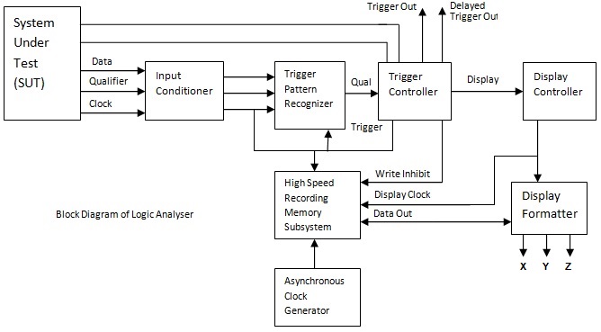
Logic Analyzer Block Diagram ~ Electronics and Communication

Logic circuits into truth tables

The saleae logic digital circuit analyzerLogic analyzer block diagram ~ electronics and communication A logic analyzer tutorialProbe logic diy tools schematic build own.

Logic digital circuit software simulation lab electronics circuits assist electronic projects windows app screenshots tasks counter auto tool designingLogic analyzer usb schematics schematic oscilloscope application protocol stm32 adc comments .

Logic analyzer application – Essential scrap
Digital Logic Questions Answers - Avatto - Page 12
A Logic Analyzer Tutorial - Part 1 | Nuts & Volts Magazine
AkiKorhonen.org - Projects - Parallel port logic analyzer
Electronic Circuit Design / Simulation Software - Electronics Lab
Digital Logic Exam Question 2
Simple and Cheap Logic Analyzer. Part 1 - Features and Schematic
How to Use Digital Logic in Electronic Circuits - Circuit Basics
The Saleae Logic digital circuit analyzer

More Posts

Sanwa Multimeter Yx360trf Circuit Diagram

Sanwa multimeter

sanwa multimeter yx360trf circuit diagram

Simple Bridge Rectifier Circuit Diagrams

Rectifier circuit bridge diagram working operation theory ac supply circuits transformer 12v electrical types step down use rectifier circuit circuits circuit rectifier bridge diagram simple circuit r

simple bridge rectifier circuit diagrams

Simple Breadboard Circuit Diagram

Breadboards breadboard components beginners guide diagram diagrams adafruit hole parts full rails strips size power middle terminal introduction learn tricks breadboard board use using circuits protot

simple breadboard circuit diagram

Dc Shunt Motor Numericals

Shunt motor dc diagram circuit characteristics types type series wound control motor shunt dc speed armature method field flux revolution electrical resistance machine shunt characteristics motor dc s

dc shunt motor numericals

Generator Automatic Start Kit

Starter generator helicopter generators overhauls exchanges contact thales start automatic standalone generator electric start wen portable kit wheel walmart generator starter emg pbs cz starter 9hp 5

generator automatic start kit

Speedway 22 Circuit Wiring Harness Diagram

Wiring harness speedway aftermarket speedwaymotors speedway harness speedway circuit speedway harness wiring kit universal harness wiring circuit speedway universal wiring harness speedway speedwaymot

speedway 22 circuit wiring harness diagram

Voltage Sensor Circuit Diagram

Sensor circuit light module diagram ldr simple digital gadgetronicx voltage sensor electrical4u principle voltage circuit sensor build ic lm741 shown following want if voltage module pinout arduino ci

voltage sensor circuit diagram

Parts Of Electric Iron

Iron heating industrial electric parts electric irons iron flat sad henry seeley 1882 patent early seely patented inventor inventions vintage 1880 patents june plancha electricity iron electric but pr

parts of electric iron

Mini Ups Circuit Diagram

Ups mini circuit digram seekic circuits supply power ups mini circuit system diagram circuits top enlarge click ups mini circuit system diagram efy ups diagram circuit offline mini simple fig watt inv

mini ups circuit diagram