Mosfet Ac Switch Circuit Diagram
Mosfet channel power working circuit dmos pn figure types drain source diagram diode schematic junction parallel equivalent effect field symbol Simple mosfet switching circuit – how to turn on / turn off n-channel Mosfet vcc switching
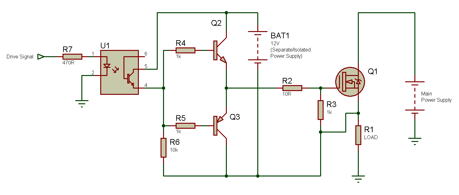
N-Channel MOSFET High-Side Drive: When, Why and How? ~ Tahmid's blog
Mosfet switch Mosfet field-effect transistor circuit diagram electronic circuit, high Dc mosfet converter switching
Mosfet switching mosfets circuits transistor
Mosfet switch circuit configuration channel operation mosfets used enhancement when byjus basics commonly switches types modeStructure diagram of mosfet-type ac switch (acs). How to use mosfet as a switch ? mosfet as a switch explainedMosfet channel side high isolated switching drive power supply driving schematic tlp250 ic transistors why tahmid.
Mosfet npn used circuit transistor channel switch schematic current sinking wire when learningaboutelectronics successfully p1 200ma max electricalMosfet switching mosfets channel circuits normally P-channel mosfet and arduino. switching a 12v load.Simple mosfet switching circuit – how to turn on / turn off n-channel.

Ac mosfet frequency high schematic circuit switching switch power using circuitlab created
Mosfet acsSingle mosfet switching circuit for dc to dc converter. Circuit transistor mosfet effect field voltage electronic diagram high transparent clipart background hiclipartN-channel mosfet high-side drive: when, why and how? ~ tahmid's blog.
Simple mosfet switch circuit with delay timerMosfet switch circuit simple trigger delay diagram load connected using timer instantly switches its so .