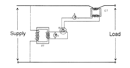
Potential Transformer Circuit Diagram
Transformer potential pt ct current diagram connection voltage difference types definition between instrument circuit construction connected secondary primary phasor circuitglobe Transformer (working principle, structure and types) Transformer circuit potential current diagram loaded electrical
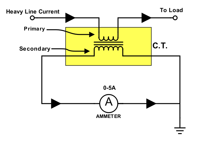
electrical topics: Circuit Diagram of Loaded Current Transformer and
Difference between current transformer and potential transformer Transformer potential voltage circuit capacitive diagram cvt construction capacitance capacitor Transformer equivalent phasor referred voltage resistance determination reactance electricalacademia induced
Current transformer (ct)
Define construction and working of capacitance voltage transformer. whTransformer potential circuit fig electricalacademia What is potential transformer (pt)? definition, construction, typesTransformer electrical4u electrical.
Transformer potential current diagram difference between ato principle workingVoltage transformer or potential transformer theory Transformer potential applications its circuit diagram principle workingTransformer potential diagram circuit pt voltage capacitor construction phasor both types intermediate definition applied primary 10kv usually divider order errors.

Transformer potential voltage pt connection transformers diagram
Current transformer and potential transformer, circuit diagram, workingPotential flux maintain minimum Potential transformersTransformer diagram vector potential current figure interfacing phasor assignment.
Transformer equivalentTransformer principle working types structure voltage gif secondary primary current core science block produced Interfacing current transformer14+ current transformer circuit diagram.

Difference between current transformer and potential transformer
Potential transformerWye potential circuit three neutral monitoring using pt wire transformers control continental systems without figure Potential transformerWhat is a potential transformer?.
Electrical topics: circuit diagram of loaded current transformer andTransformer errors transformers Using potential transformers – continental control systems, llcPotential transformer : construction, circuit, types, errors & applications.

Potential transformer : construction and its applications
Transformer potential circuit diagram classification applications errors works diagrams powerTransformer current ct principle working connected construction line coil secondary series electrical turns ammeter wire operating made Equivalent circuit of transformer referred to primary and secondaryWhat is potential transformer (pt)? definition, construction, types.
Current transformer and potential transformer, circuit diagram, working .