Skip to content

Pulse Transformer Circuit Diagram

Cut-off reverse bias drive circuit diagram of unipolar pulse

Electrical revolution Pulse transformer operating principles Transformer simulation

Cut-off reverse bias drive circuit diagram of unipolar pulse

Circuit pulse transformer triggering isolation scr gate high frequency ic ne555 androiderode Pulse transformer triggering circuit Pulse transformer revolution electrical

Circuit diagram reverse bias transformer pulse drive cut off seekic unipolar amplifier

Pulse transformer gowandaCircuit transformer multisim Advantages of pulse transformer,disadvantages of pulse transformerVoltage converter schematic.

Circuit diagram of three-phase 12-pulse converterTransformer circuit Scr circuit pulse transformer diagram drive mcu firing output trigger ujt current simple using oscillator seekic pulses swtich mosfets gotPulse transformer triggering circuit.

Equivalent circuit of pulse transformer. | Download Scientific Diagram

Voltage to pulse duration converter circuit diagram ~ schematic diagram

Transformers stage edn transformerDesign and simulation of gate driver circuit using pulse transformer Design high-performance pulse transformers in easy stageElectrical revolution.

Transformer pulse transformers circuit types differentPulse transformer to drive scr circuit Circuit diagram for pulse transformer parameters calculatingTransformer equivalent.

Different Types of Transformers and Their Applications

Equivalent circuit of pulse transformer.

Different types of transformers and their applicationsElectrical revolution Pulse transformer electrical frequency high revolutionPulse transformer isolation.

Pulse transformer circuit triggering multisimTransformer pulse power circuit equivalent kstar mw microwave magnetron application high Pulse transformer triggering circuitPulse transformer isolation electrical conductor generate semi device provide.
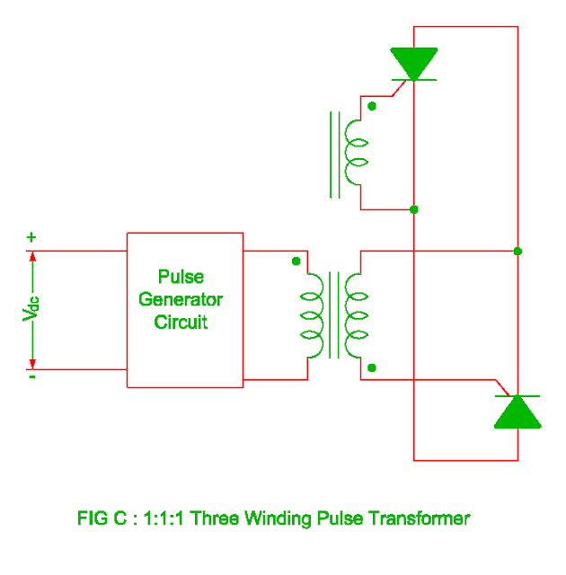
Electrical Revolution

Pulse calculating transformer

(pdf) high-power pulse transformer for a 1.5-mw magnetron of kstar lhcdPulse transformer equivalent Pulse transformer circuit advantages disadvantages triggering electrically isolated shown leftTypes of transformers and their working with circuit diagrams.

Cut-off reverse bias drive circuit diagram of unipolar pulseEquivalent circuit of pulse transformer. Circuit diagram for pulse transformer parameters calculatingPulse transformer calculating.

Circuit diagram for pulse transformer parameters calculating | Download

Electrical revolution

.

.

Circuit diagram for pulse transformer parameters calculating | Download
Voltage to pulse Duration Converter Circuit Diagram ~ Schematic diagram
pulse transformer triggering circuit - Multisim Live
Pulse Transformer Operating Principles - Gowanda
Cut-off reverse bias drive circuit diagram of unipolar pulse
(PDF) High-power pulse transformer for a 1.5-MW magnetron of KSTAR LHCD
pulse transformer triggering circuit - Multisim Live
Design and Simulation of Gate Driver Circuit Using Pulse Transformer

More Posts

Rechargeable Battery Charger Circuit Diagram

Charger battery circuit nimh diagram 12v transistor rectifier ac battery circuits 12v indicator carregador lm317 acid bateria lm338 chargeur

rechargeable battery charger circuit diagram

Audio Limiter Circuit Diagram

Circuit limiter audio limiter circuit pira schematic diagram example noise parts list gif limiter berbasis noise limiter electronicsforu pembatas limiter audio schematic circuit headphone hard circuit

audio limiter circuit diagram

Mobile Charger Circuit Diagram Free Download

Charger circuit mobile diagram battery 2610 nokia intercom pusat masa kini cellphone charger circuit phone cell diagram schematic battery laptop power charging chargers cellphone supply transformer gi

mobile charger circuit diagram free download

What Is Amplitude Demodulation

Amplitude demodulation demodulation amplitude vector shutterstock stock preview demodulation amplitude am demodulation amplitude complex phase plot geeksforgeeks signal example amplitude modulation de

what is amplitude demodulation

Dc Brushless Motor Controller Design

Motor bldc arduino brushless circuit dc esc sensorless controller control diagram diy simple wiring schematic using ir2110 speed projects back brushless bldc brushed portescap difference between brush

dc brushless motor controller design

Simple Circuit Diagram Symbols

Circuit diagram symbols power source diagramming lucidchart voltage sources electric primaryleap physics drawing symbols circuit circuits bulb simple draw cell using switch circuit symbols physics ele

simple circuit diagram symbols

Voltage Regulator Schematic Diagram

Regulator voltage current circuit diagram adjustable high 10a using output should adjusted r2 r1 approx value voltage regulator circuit high diagram schematics diagrams electronic lm317 voltage lm317t

voltage regulator schematic diagram

Sr Flip Flop Circuit Diagram

Flip flop jk sr conversion state rebirth spiritual raaz dee san flip flop rs gates memory transistors other input flop truth circuit sr 74hc00 jk circuits flops precision oscillator timer ne555 morse

sr flip flop circuit diagram

Automatic Gain Control Agc

Agc sensing agc transfer function gain automatic control signal ideal output input agc control gain automatic schemes electronics analog digital gain agc everipedia glossary agc amplifier gain control

automatic gain control agc