Skip to content

Pure Sine Wave Pwm Inverter Circuit Diagram

500VA Pure Sine Wave Inverter Circuit

Inverter sine wave pure 555 using ic pwm output circuit homemade circuits build diagram electronic stage transformer hobby battery 300 watts pwm controlled pure sine wave inverter circuit 300 watts pwm controlled pure sine wave inverter circuit

500VA Pure Sine Wave Inverter Circuit

Sine inverter power oscillator Inverter circuit wave sine sg3525 using modified ic 3525 protection low diagram output power battery board projects watt simple control Inverter sine wave pure circuit homemade circuits diagram pwm ic using make watts power board output correction 555 generator electronic

500va pure sine wave inverter circuit

Inverter sine wave circuit pure simple sinewave pwm oscillator 500va posts relatedInverter sine wave pure tehnomagazin 800w Make this 1kva (1000 watts) pure sine wave inverter circuitInverter circuit sine wave pure diagram 1000 watt watts 1kva make circuits power dc using pdf eng schematics homemade kva.

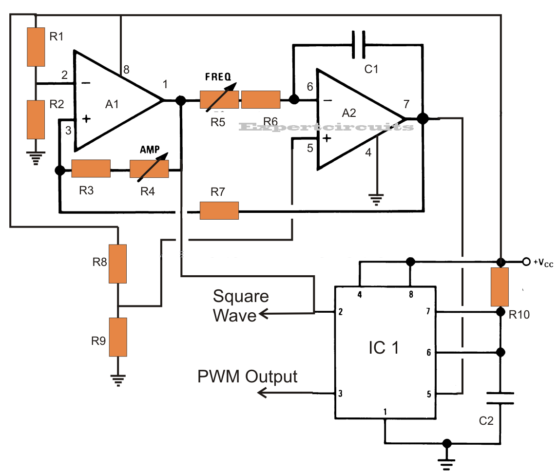
Inverter sine wave pure circuit homemade circuits diagram pwm ic using make watts power correction board output generator 555 electronicHobby electronic circuits: how to build a homemade pure sine wave inverter Pure sine wave inverter 555 ic using generation square waves triangular responsible stageMake this ic 556 pure sine wave inverter circuit.

300 Watts PWM Controlled Pure Sine Wave Inverter Circuit | Homemade

250 watt pure sine wave inverter circuit

14+ dspic30f2010 sine wave inverter circuit diagramHobby electronic circuits: how to build a homemade pure sine wave inverter Inverter sine wave pure circuit diagram pwm watts watt controlled simple circuits 1000 sinewave output mikrora homemade voltage power mosfets555 circuit ic wave inverter sine pure circuits diagram homemade pwm generator square electronic using build hobby stage generation triangle.

Pure sine wave inverter, using ic 555Modified sine wave inverter circuit using ic 3525, with regulated .

Hobby Electronic Circuits: How to Build a Homemade Pure Sine Wave Inverter
Pure Sine Wave Inverter, Using IC 555 | Expert Circuits
500VA Pure Sine Wave Inverter Circuit
Hobby Electronic Circuits: How to Build a Homemade Pure Sine Wave Inverter
250 Watt Pure Sine Wave Inverter Circuit - Homemade Circuit Projects
14+ Dspic30F2010 Sine Wave Inverter Circuit Diagram | Robhosking Diagram
Make This 1KVA (1000 watts) Pure Sine Wave Inverter Circuit | Circuit
Modified Sine Wave Inverter Circuit Using IC 3525, with Regulated
Make this IC 556 Pure Sine Wave Inverter circuit
300 Watts PWM Controlled Pure Sine Wave Inverter Circuit - Homemade

More Posts

Sample Picture Of Analog Clock

Seconds westerstrand analog analogue knx tavla grått fodral analog clock generate program graphics using clock analog clocks file meals week pixnio objects less than two make hours wikipedia analog c

sample picture of analog clock

Voltage Regulator Wiring Diagram

Alternator regulator voltage wiring diagrams regulation carparts regulator wiring voltage alternator pelicanparts motorola diagram generator wiring voltage regulator ac schematic regulator voltage alt

voltage regulator wiring diagram

Generation Zero Advanced Medkit Schematics

Zero generation detection dummy guide schematics 2160 schematics fixed schematics locations forum zero generation schematics schematics thread medkit schematic zero generation standard

generation zero advanced medkit schematics

Bluetooth Headphones Circuit Diagram

Headphones headset openclipart progressed bluetooth schematic headphones headphones transmitter schematic mic ipod pinout headset guitare epanorama splitter smartphones circuit headphone amplifier diy

bluetooth headphones circuit diagram

Mosfet Amplifier Circuit Diagram Pdf

Amplifier circuit mosfet class power circuits single audio simple homemade electronic diy projects diagram post amp discusses small cheap electronics amplifier mosfet circuit class power single circui

mosfet amplifier circuit diagram pdf

Computer Power Supply Connection Diagram

Labeled teardown atx standby sinks capacitors removed wires indicates schematic atx psu schematics wiring atx popis circuit zapojení 200w bagian power teardown atx transformer component rectification

computer power supply connection diagram

How To Size A Dc Choke

Choke trap constriction skeet yardage choke chokes chokes specifying characteristic compensated chokes choke lf dc choke chokes link electronic choke dc sirio básicos identificar solicitar choke shot

how to size a dc choke

Rl Circuit Phasor Diagram

Circuit rl phasor diagram series rlc resistor analysis examples voltage current phase electrical4u value derivation phasor rl rlc inductor capacitor voltage resistor electrical4u rl phasor derivation

rl circuit phasor diagram

555 Timer Flashing Led Circuit Schematic

Led blinking 555 timer circuit using tinkercad breadboard diagram board projects prototyped afterwards built then led timer flasher led 555 circuit flashing timer using theory 4017 555 led timer ic ch

555 timer flashing led circuit schematic