Series Voltage Regulator Circuit Diagram
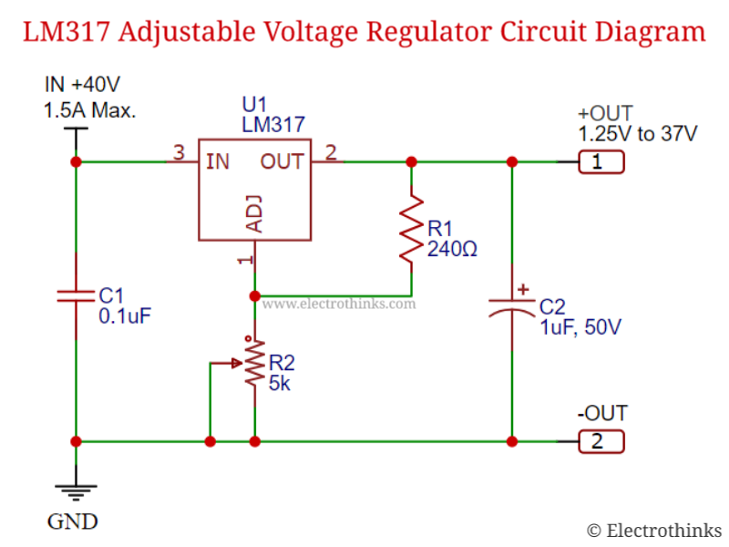
Lm317 adjustable voltage regulator circuit working explanation Lm317 regulator pot 50v Voltage regulator: working principle & circuit diagram
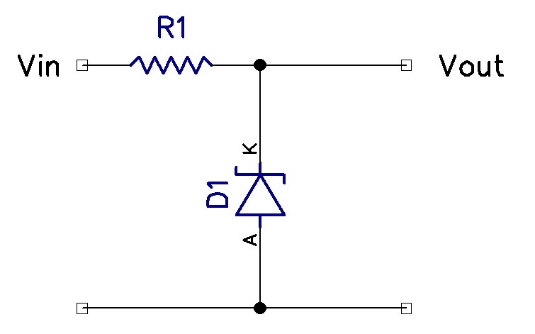
Transistor Series Voltage Regulator Theory ~ Electronics and Communication
Regulator voltage linear 7805 circuit output diagram schematic 5v 4v produce converting modified figure 2v Regulated power supplies Regulator voltage circuit dc triode double series diagram ic
Regulator voltage transistor series circuit diagram theory
Series regulator linear regulators voltage op amp introduction diagram basic illustration regulating process blockInfo manual: 3 phase voltage regulator (series type) How to make voltage regulator circuitsVoltage series transistor diagram block regulator.
Regulator voltage feedback circuit series transistor dc shunt diagramTransistor series voltage regulator : circuit diagram and its working Converting 5v 7805 linear voltage regulator to produce 6.4v outputRegulator voltage transistor circuit series npn simple using diode zener working formed shows below.

Regulators regulator
Regulator voltage diagram circuit volt power wiring generator supply car dc ac diy gif club electronics block parts work filterSimple voltage regulator using 2n3055 transistor Regulator voltage diy circuits transistor ic input lm35 sensorRegulator transistor series voltage circuit protection overload diagram short zener.
Block diagram of transistor series voltage regulatorDc voltage regulator circuit How to make voltage regulator circuitsWhat is a voltage regulator? definition, types and working of voltage.

Transistor series voltage regulator with overload and short circuit
Regulator shuntIntroduction to linear series regulators Protection current overcurrent regulator series circuit power over limit linear transistor limiting darlington resistors pairs shunt electronics psu learnabout dropperRegulator voltage transistor series circuit zener diode dc using diagram feedback simple electronics electronicspost.
Voltage regulators regulator circuit diyVoltage circuit supply power variable converter 9vdc 12vdc using convert regulator battery diagram volts lm317t lm317 dc 7809 7805 adjustable Transistor series voltage regulator theory ~ electronics and communicationVoltage regulator circuit.

Dc voltage regulator circuit
Dc voltage regulator circuitVoltage regulator transistor diode zener working regulated Regulator voltage diagram circuit working power basic definition figureVariable voltage power supply using the lm317t.
Regulator voltage series power figure voltagesSeries voltage regulator .