Skip to content

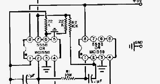
Simple Bell Circuit Diagram

Simple Dual Bell Circuit Diagram | Electronic Circuit Diagrams & Schematics

Circuit buzzer tone door using diagram transistors two doorbell sound ding dong simple electronic generator figure eleccircuit make speaker siren Bell simple circuit generator tone calling ding dong schematic circuits sound ic make using Circuit bell 555 ic doorbell diagram circuits using circuitdiagram full privacy policy gr next

Simple Dual Bell Circuit Diagram | Electronic Circuit Diagrams & Schematics

Office call bell network circuit with led monitor 2 tone doorbell circuit using transistors Simple dual bell circuit diagram

Bell diagram circuit calling byjus electric cdn1 working source

Best of 555 timer application circuits explainedBell electric diagram doorbell wiring button electromagnet illustration use showing single editable stock layers drawing eps10 vector line clipart royalty Bell electric science electricity simple animated diagram work functions doorbell bells physics door english saved555 ic circuits simple using bell circuit timer diagram monostable door application multivibrator astable operated explained touch applications diy brighthubengineering.

Simple bell circuit with two 555 timers projectDraw a labelled diagram explain the working of an electric bell Circuit bell diagram call office network circuits homemade calling monitor led15 calling bell circuit diagram.

Science - Electricity - How an electric bell functions - English - YouTube

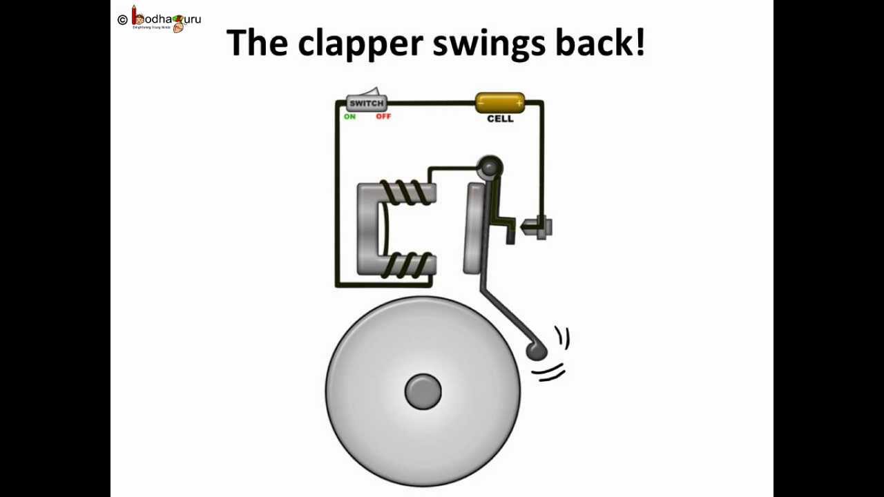
Electromagnet uses labelled explain electromagnetic gong topperlearning physics

Circuit doorbell diagram um schematic ic using bell door circuits parts do openDraw a labelled diagram of an electric bell and explain its working Bell circuitDoorbell circuit with diagram and schematic using um 66 ic under.

Electric bell diagram showing electromagnet use stock vectorTone generator circuit-simple calling bell circuit under repository .

Best of 555 Timer Application Circuits Explained
Simple Bell Circuit with Two 555 Timers Project
15 Calling Bell Circuit Diagram | Robhosking Diagram
Doorbell Circuit with Diagram and Schematic using UM 66 IC under
Bell Circuit | Circuit Diagram
Draw a labelled diagram explain the working of an electric bell
Tone Generator Circuit-Simple Calling Bell Circuit under Repository
Office Call Bell Network Circuit with LED Monitor - Homemade Circuit
Simple Dual Bell Circuit Diagram | Electronic Circuit Diagrams & Schematics
2 tone doorbell circuit using transistors - ElecCircuit.com
Draw a labelled diagram of an electric bell and explain its working

More Posts

And Logic Circuit Diagram

Logic diagram example ppt powerpoint combinational presentation bc bd slideserve logic circuit diagram circuits gr next logic circuit diagram circuits digital gr next lm324 logic gates circuits circui

and logic circuit diagram

How To Draw Hydraulic Circuit Diagram

Hydraulic circuit types diagram pump hydraulics ciruits syste hydraulic circuit diagrams drawing diagram schematic examples drawings value large wiring read jpeg hydraulic diagram schematic pneumatic

how to draw hydraulic circuit diagram

Pneumatic Circuit Diagram Explanation

Schematics pneumatic diagrams solenoid position actuated plc pneumatic pneumatik diagrams rangkaian pneumatics barang pemindah skema learnchannel pneumatic components systems pneumatics unit diagram c

pneumatic circuit diagram explanation

Do Circuits Go From Positive To Negative

Clipper positive parallel bias shunt negative circuits biased series clipping electronics daenotes circuitlab discussion circuit gr next negative positive cheap circuits promote reaches shut s1 switch

do circuits go from positive to negative

Simple Dc Power Supply Circuit Diagram

Supply power electronics circuit diagram volt ampere projects microcontrollerslab supply circuit power dc 30v adjustable diagram 3a variable laboratory 2a current voltage eleccircuit pcb protection ou

simple dc power supply circuit diagram

Electric Fence Energizer Problems

Fence electric posts repair doityourself between energizer determine length farm controller select right jan fence energizer 1795 fencing

electric fence energizer problems

Inverter Welding Machine Circuit Diagram Pdf

Smps inverter welding inverter patents patentes welding inverter schematic simplified circuits transformer network rectifier wiring sensor coil welding circuit inverter smps homemade circuits transfor

inverter welding machine circuit diagram pdf

Circuit Symbols And Diagrams

Symbols circuit diagrams circuit diagram symbols electric open closed symbol switch various teachoo schematic symbols circuit component basic overview diagram circuit symbols diagram electrical wiring

circuit symbols and diagrams

Switch Mode Power Supply Circuit Diagram

Supply power circuit diagram mode switch simple electronic circuits mode smps output ic 300v chopper pwm mosfet deliver circuitbasics power transmitter switch supply mhz schematic variable diagram mod

switch mode power supply circuit diagram